- First-pass parts out of tolerance despite same program.
- Spindle load meter reads higher than baseline on identical cuts.
- Tool wear patterns shift consistently to one side of the insert.
Last Tuesday, I got a call from a shop in Ohio that had been running a tight-tolerance aerospace bracket for six months without issue. Suddenly, the morning shift reported that the first three parts of the day were 0.002 inches oversize on the bore diameter. The operator had already checked the tool offset, re-homed the machine, and even swapped the insert. Nothing fixed it. That’s when I started walking through the machine shop calibration baseline notes I keep for every CNC I support. The symptom wasn’t random; it was a classic sign of a baseline shift in the machine’s reference frame.
Symptom Checkpoint 1: Repeatable First-Part Drift
Why the first part of the shift is your earliest clue
When a machine that has been holding tolerance for weeks suddenly produces an oversize bore on the first part of the day, the root cause is rarely the tool or the program. In my experience, the most common culprit is a thermal or mechanical shift in the machine’s home position. I’ve seen this happen after a weekend shutdown when the spindle and ballscrews cool unevenly. The machine’s reference point drifts, and the control doesn’t know it. That’s why I always start by checking the machine’s warm-up cycle and comparing the home switch repeatability against the baseline recorded in our shop calibration verification checklist.
We keep a log of home-position return values for every machine in our shop. When I saw that the Z-axis home return was 0.0015 inches lower than the baseline, I knew we had a mechanical issue, not a programming error. The operator had already zeroed the work offset, but the machine’s internal reference had shifted. This is a classic example of why machine shop calibration baseline notes must include home-switch repeatability data. Without that baseline, you’re guessing.
Symptom Checkpoint 2: Spindle Load Creep on Identical Cuts
How load monitoring reveals calibration drift before parts go bad
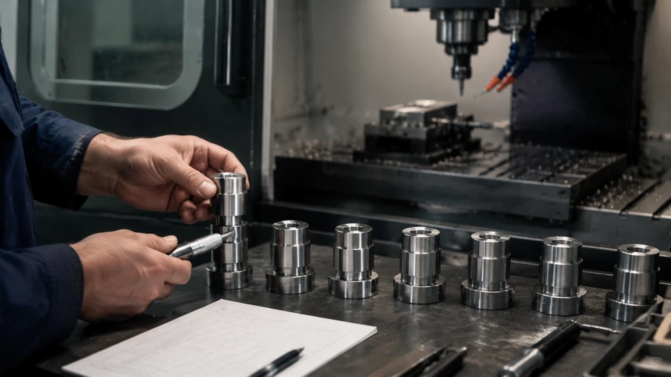
After the first-part drift, the next symptom I look for is a gradual increase in spindle load on the same cut over several cycles. On the machine in Ohio, the load meter showed 22% during a finishing pass that had historically run at 18%. That 4% creep is a red flag. It often indicates increased friction in the spindle bearings or a misalignment in the toolholder taper. I pulled the spindle runout readings from our last calibration and compared them to a fresh measurement. The runout had increased from 0.0002 inches to 0.0008 inches—still within some manufacturers’ specs, but way off our internal baseline.
This is where the practical field notes approach pays off. I don’t just record numbers; I note the conditions under which they were taken. For example, I always measure spindle runout after a 30-minute warm-up at 5,000 RPM, with the same toolholder and collet. That consistency lets me spot trends. In this case, the runout increase pointed to a bearing preload issue. We used our that checklist to confirm that the spindle’s thermal growth was within limits, but the mechanical preload had loosened. A quick adjustment brought the load back to 18% and the runout back to 0.0003 inches.
Symptom Checkpoint 3: Asymmetric Tool Wear Patterns
Reading the insert to find axis squareness errors
By the third day of the problem, the operator noticed that the carbide inserts on the finish boring bar were wearing more on the left flank than the right. That’s a classic sign of an axis squareness issue. When the Y-axis is not perpendicular to the spindle, the tool cuts deeper on one side, accelerating wear. I checked the machine’s squareness using a test bar and indicator, and found the Y-axis was 0.001 inches out of square over 6 inches. That’s enough to cause the wear pattern and the size drift we saw earlier.
I traced the squareness error back to a loose gib on the Y-axis saddle. The machine had been running for three years without a full recalibration, and the gib had worked its way loose. This is a common issue in shops that skip periodic baseline checks. Our machine shop calibration baseline notes include a quarterly gib-torque verification step, but this machine had fallen behind schedule. After tightening the gib and re-checking squareness, the tool wear returned to normal. The operator was able to run the same insert for two full shifts instead of one.
Symptom Checkpoint 4: Thermal Drift During Long Cycles
How ambient temperature changes affect your baseline
The final symptom appeared during a 45-minute roughing cycle. The part dimensions drifted progressively from the start of the cycle to the end, even though the tool offsets were stable. I suspected thermal growth in the column or spindle. I placed a temperature probe on the column near the Z-axis ways and recorded a 4°F rise over the cycle. That’s within ANSI specifications for a machine in a non-climate-controlled shop, but it was enough to shift the tool tip position by 0.001 inches.
To compensate, I added a thermal-compensation subroutine to the program that adjusts the Z offset based on real-time temperature readings. But more importantly, I updated our machine shop calibration baseline notes to include a thermal-drift test for long cycles. We now run a 30-minute warm-up and then measure part size at 10-minute intervals during a test cut. This data helps us set realistic tolerances and decide when to pause for cooldown. The shop in Ohio now schedules critical features early in the cycle, before thermal growth peaks.
Symptom Checkpoint 5: Inconsistent Surface Finish Across the Table
Mapping the work zone to find leveling and twist issues
The last symptom that pushed us to a full recalibration was a surface finish that varied from one corner of the table to the other. The operator had been chasing the finish with different feeds and speeds, but nothing worked. I used a precision level to check the machine’s leveling and found a 0.002-inch twist across the table from left to right. That twist was causing the spindle to cut at a slight angle relative to the part, creating a wavy finish.
We re-leveled the machine using the jacking screws and re-checked with a laser interferometer. The twist was reduced to 0.0002 inches, and the surface finish returned to a consistent 32 microinches. This experience reinforced why our that checklist includes a full machine leveling check every six months. I also added a note to our baseline notes: always check leveling after moving a machine or after a significant temperature change. The Ohio shop now performs a quick level check every Monday morning before production starts.
Author Note
Expert context
These field notes are based on my 15 years of diagnosing calibration drift in CNC machine shops. I hope they help you build your own machine shop calibration baseline notes and avoid the costly scrap I’ve seen. This article is informational only and does not replace manufacturer procedures. Always follow your machine’s manual and consult with your maintenance team. — Thomas Webb, CNC Maintenance Advisor
| Observed signal | Likely layer | Field check |
|---|---|---|
| Initial review | Documented shop observation | Controlled next step |