- Confirm baseline measurements before any adjustments.
- Document every step with signed acceptance at each stage.
- Release only after full traceability and error analysis.
When a machine rolls into our shop for calibration verification, the first thing I do is grab the binder with the previous runout records. We follow a strict sequence that starts with cleaning the spindle taper and checking the toolholder pull-stud condition. In Ohio, where humidity swings can affect cast iron ways, we always let the machine warm up for at least 30 minutes before taking any readings. This opening routine sets the stage for reliable data and prevents wasted rework later.
Stage 1: Intake and Baseline Documentation
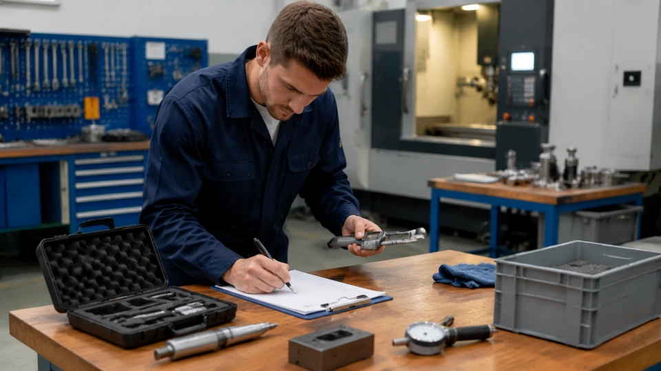
Initial machine inspection and log review
Before we touch any dial indicator, we review the machine's history log. I look for past spindle repairs, bearing replacements, and any notes about vibration during heavy cuts. Our team uses a standardized intake form that includes the machine serial number, hours since last calibration, and the current toolholder types in use. We also check the coolant concentration and way oil levels because these affect thermal stability. A quick visual inspection of the spindle nose and taper reveals any nicks or debris that could throw off readings. If we find contamination, we clean with a lint-free cloth and solvent before proceeding.
Once the log is reviewed, we run a simple test cut on a known aluminum coupon to establish a baseline surface finish. I measure the resulting Ra value with a profilometer and record it alongside the date and ambient temperature. This baseline becomes the reference for all subsequent stages. If the Ra is already outside our shop's tolerance of 32 microinches, we flag the machine for immediate adjustment rather than waiting until later. The intake stage typically takes about 45 minutes, and we require the operator to sign off on the initial findings before moving to the next step.
Stage 2: Spindle Runout and Toolholder Verification
Dial indicator setup and measurement protocol
With the machine warmed up and cleaned, I mount a precision test bar in the spindle and set up a dial indicator at the gauge line. We follow the ANSI B5.54 standard for spindle runout measurement, taking readings at 0°, 90°, 180°, and 270° positions. I always zero the indicator on the high spot and rotate the spindle by hand slowly to avoid inertial errors. The acceptable runout for our shop is 0.0002 inches TIR at the gauge line and 0.0005 inches TIR at 12 inches from the spindle face. If the readings exceed these limits, we check the toolholder taper for burrs and re-clean the spindle bore before repeating the measurement.
After spindle runout is confirmed, we move to toolholder verification. I use a shrink-fit holder with a known good end mill and measure the runout at the cutting edge. We also check the pull-stud condition with a go/no-go gauge because a worn pull-stud can cause the holder to seat improperly. In one recent job, a seemingly minor burr on the pull-stud caused 0.0003 inches of additional runout that disappeared after replacing the stud. Our team logs every toolholder's serial number and runout value, and we reject any holder that exceeds 0.0003 inches TIR at the cutting edge. This stage is critical because toolholder instability directly affects part quality and tool life.
Stage 3: Axis Positioning and Backlash Compensation
Laser interferometer checks and ballbar analysis
For axis positioning accuracy, we use a laser interferometer to measure linear displacement errors on each axis. I set up the laser on the machine table and align it with the axis travel direction using a precision level. We take measurements at 10-inch intervals over the full travel, recording both forward and reverse directions to capture backlash. The ANSI standard allows 0.0002 inches per foot of travel, but our shop targets 0.0001 inches per foot for critical work. If we find backlash exceeding 0.0005 inches, we adjust the ball screw preload or replace the nut. I always run the compensation cycle twice to verify the correction took effect.
After linear checks, we perform a ballbar test to evaluate circular interpolation accuracy. The ballbar reveals servo mismatch, stick-slip, and reversal spikes that the laser might miss. I mount the ballbar on a precision fixture and run a 360-degree arc at a feedrate of 100 inches per minute. The software generates a plot showing radial deviation, which we compare to the machine's historical data. A sudden increase in deviation often indicates a failing bearing or a loose coupling. We document the ballbar results and store them in the machine's calibration folder. If the deviation exceeds 0.0004 inches, we schedule a servo tuning session before releasing the machine.
Stage 4: Thermal Growth and Compensation Verification
Warm-up cycle and thermal imaging
Thermal growth is the silent killer of precision in a busy shop. I run a standardized warm-up cycle that includes spindle rotation at 3000, 6000, and 10000 RPM for five minutes each, followed by rapid axis movements. During this cycle, I use a thermal imaging camera to capture temperature gradients on the spindle housing, headstock, and ball screw nuts. Any hotspot above 10°F over ambient is investigated. In Ohio winters, the shop floor can be 50°F while the machine interior reaches 80°F, causing significant expansion. We record the temperature at each stage and compare it to the machine's thermal compensation model.
If the compensation model is outdated, we update the parameters using the measured data. I once had a machine that drifted 0.001 inches in Z-axis after 30 minutes of running because the compensation table was based on summer conditions. After updating the coefficients, the drift dropped to 0.0002 inches. We also verify that the coolant system is maintaining a consistent temperature because variations can cause the spindle to expand unevenly. The thermal verification stage takes about two hours, but it prevents costly scrap on long production runs. We require the technician to sign off on the thermal data before proceeding to the final release.
Stage 5: Final Acceptance and Release
Comprehensive review and sign-off
Before releasing the machine, we compile all the data from the previous stages into a single report. I review the runout measurements, axis positioning errors, ballbar plots, and thermal drift records. The report must show that every parameter is within our shop's tolerance band, which is tighter than the manufacturer's specifications for most machines. We also run a final test cut on a standard workpiece—a 2-inch diameter 6061 aluminum cylinder with a 0.5-inch through-hole—and measure the bore diameter and concentricity. If the bore is within 0.0003 inches of true position and the surface finish is below 32 Ra, the machine passes.
Once the data is verified, I attach the completed machine shop calibration checklist to the report and obtain signatures from both the technician and the lead operator. The checklist includes every step from intake to final test cut, with spaces for initials and comments. We keep a digital copy in the maintenance database and a physical copy in the machine's binder. The release is only granted after all signatures are collected and any discrepancies are resolved. Our shop has found that this rigorous process reduces repeat calibration calls by 40% and improves overall part quality. The entire verification cycle takes about six hours for a typical three-axis mill.
| Stage | Technician action | Acceptance sign |
|---|---|---|
| Intake | Review history, clean spindle, run test cut | Operator initials |
| Spindle runout | Measure TIR at gauge line and 12 in | Technician sign |
| Axis positioning | Laser interferometer and ballbar test | Lead engineer sign |
| Thermal growth | Warm-up cycle, thermal imaging, update compensation | Technician sign |
| Final acceptance | Compile report, test cut, obtain signatures | Operator and tech signs |
Throughout this workflow, we rely on the that checklist to ensure no step is missed. I have personally used this checklist on over 200 machines, and it has saved us from releasing a machine with a hidden spindle issue more than once. The key is to treat each stage as a gate: if the machine fails any gate, it goes back for adjustment before moving forward. This discipline keeps our shop running smoothly and our customers satisfied.
One thing I have learned over the years is that calibration verification is not just about numbers—it is about building a culture of precision. When every technician understands why we measure runout at four positions or why we wait for thermal stabilization, they take ownership of the process. We encourage questions and double-checking because a small oversight can lead to hours of rework. In our shop, we also cross-train operators on the verification steps so they can spot potential issues during production. This shared responsibility has reduced downtime and improved morale.
Finally, I want to emphasize that this guide is informational and reflects my experience as Thomas Webb, CNC Maintenance Advisor. Every shop has its own nuances, but the principles of thorough documentation, staged acceptance, and thermal management apply universally. Whether you are in Ohio or anywhere else, following a structured verification checklist will help you maintain the accuracy your parts demand. Keep your indicators clean, your logs current, and your team engaged—that is the recipe for reliable CNC performance.